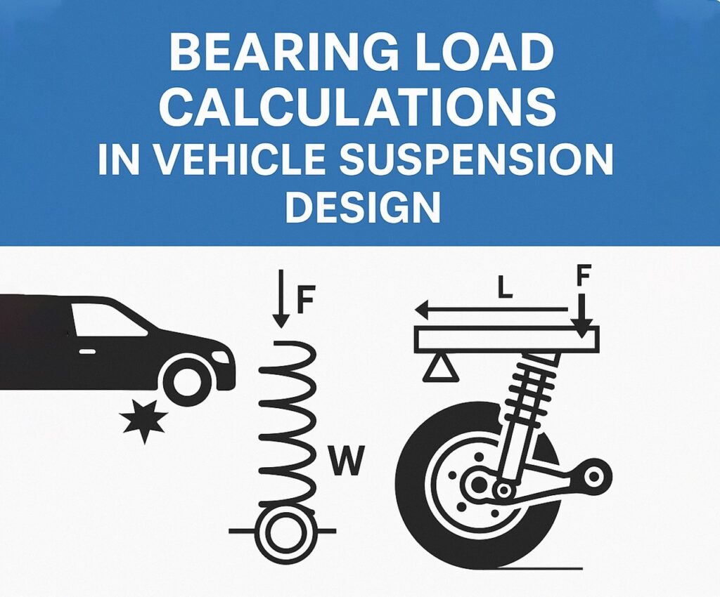
In modern automotive engineering, precision in wheel hub, hub assy wheel, and wheel bearing and hub design is essential for optimizing suspension performance. These components are not just mechanical necessities; they define how loads transfer from the road to the chassis. Without accurate bearing load calculations, even the best suspension designs risk premature failure, poor handling, or safety issues. Understanding how loads distribute and affect the wheel hub, hub assy wheel, and wheel bearing and hub systems is critical for reliable, efficient vehicle performance. Know More
Why Bearing Load Calculations Matter
Suspension systems are designed to absorb and manage dynamic forces: cornering loads, braking forces, vertical bumps, and road irregularities. The wheel hub, hub assy wheel, and wheel bearing and hub are load transmission points that ensure these forces don’t directly impact the chassis or passenger comfort. Without accurate load calculations, bearings may wear unevenly, leading to noise, increased rolling resistance, or even wheel failure.
Types of Loads Acting on Bearings
When calculating loads on wheel hub assemblies, engineers consider:
- Radial loads: Perpendicular to the axle, caused by vehicle weight and road bumps.
- Axial loads: Parallel to the axle, caused by cornering or braking.
- Combined loads: Real-world forces rarely act in isolation. Every hub assy wheel must be tested under simultaneous axial and radial stress.
The wheel bearing and hub design must balance all three. Skimping on calculations leads to under-designed components or unnecessary weight.
The Role of Vehicle Dynamics
Vehicle dynamics dictate how forces translate through the suspension and into the wheel hub. A lightweight sports car with stiff suspension transmits more instantaneous force into the wheel bearing and hub. A heavy SUV designed for comfort distributes forces differently. That variance affects bearing sizing, placement, and material choice.
For example, a mid-size sedan’s front hub assy wheel might see different load profiles due to front-wheel drive configurations than the rear. Calculating these load paths allows engineers to optimize each component individually.
Modern Tools and Simulation Techniques
Gone are the days of simple static calculations. Engineers now use advanced Finite Element Analysis (FEA) to model how each wheel hub responds under load. Simulation inputs include:
- Vehicle speed
- Cornering radius
- Wheel size
- Material properties
- Suspension geometry
With these, they can predict fatigue life, thermal response, and performance degradation. For instance, a poorly designed wheel bearing and hub may perform well at low speeds but overheat or deform during sustained highway driving.
Load Calculation Process
Here’s a simplified version of how bearing loads are calculated:
- Determine vehicle weight distribution: Including driver, passengers, cargo.
- Calculate static loads: Based on gravitational force per corner.
- Factor in dynamic loads: Braking, cornering, and acceleration forces.
- Account for steering and camber effects: Which alter load vectors.
- Apply safety margins: Typically 1.5 to 3x expected max load.
With the results, the wheel hub and hub assy wheel designs are refined for structural integrity and service life.
Real-World Application Example
Let’s take a compact SUV with a curb weight of 1600 kg. Assuming even weight distribution, each hub assy wheel supports 400 kg statically. Under hard braking (deceleration of 1g), the front wheel bearing and hub assemblies can momentarily experience double that, or 800 kg equivalent load. Add in a cornering force of 0.6g, and the axial loads increase.
In this case, a tapered roller bearing might be selected due to its better performance under combined loading. Engineers may even redesign the wheel hub flanges to disperse stress more efficiently.
Design Innovations Driving Change
Several new approaches are reshaping wheel hub and wheel bearing and hub development:
- Integrated sensors: Modern hub assy wheel designs now often include ABS, traction, or even tire pressure sensors. Load calculations must now factor in not just mechanical strength, but also vibration that could affect sensor readings.
- Composite materials: Some manufacturers are experimenting with carbon-reinforced polymer wheel hub components to save weight without compromising strength.
- Modular bearing systems: These allow for easier replacement and standardization across models, but require precise load distribution analysis to prevent failure.
How Poor Load Calculations Show Up in the Real World
Improper bearing load design leads to:
- Wheel noise: High-frequency whining due to uneven stress.
- Vibration: Particularly under acceleration or braking.
- Overheating: Especially during extended high-speed driving.
- Component fatigue: Leading to cracked hub assy wheel mounts or warped wheel bearing and hub shells.
Tips for Automotive Engineers and Designers
- Don’t ignore real-world conditions. Simulations are great, but track testing with instrumentation validates those numbers.
- Over-design with purpose. Don’t just increase strength; analyze where it’s actually needed.
- Design for serviceability. Make wheel hub and hub assy wheel components modular when possible.
- Optimize for noise, vibration, harshness (NVH). Your wheel bearing and hub can impact cabin comfort more than expected.
The Future of Bearing Load Analysis
AI-driven optimization is the next frontier. Software can now suggest optimal geometries and materials for wheel hub systems in minutes, factoring in millions of variables that used to take days to test. Combined with real-time data from smart sensors, future hub assy wheel components may self-adjust to changing loads.
Electric vehicles also change the game. With heavy battery packs and regenerative braking, the wheel bearing and hub assemblies see different load profiles entirely. Designers are responding with next-gen bearings that can take both mechanical and electrical stress.
Conclusion
Accurate bearing load calculations are no longer optional—they’re foundational. With vehicles becoming faster, heavier, and more connected, the humble wheel hub, hub assy wheel, and wheel bearing and hub have to do more work than ever before. But with smarter design, better simulations, and a real-world mindset, engineers can deliver safer, quieter, and longer-lasting suspension systems.
If you’re designing or evaluating a vehicle suspension system, don’t overlook the importance of every wheel hub, hub assy wheel, and wheel bearing and hub. They aren’t just components—they’re the backbone of control and confidence on the road.

